Seismometers for Schools and Others on a Budget!

TC1 VIII Oct. 2011


The original TC1 vertical seismometer was encased in 3″ ABS plumbing pipe.

This served two functions: (1) it enclosed the spring, protecting it from drafts;

(2)it served as a skeleton or frame on which the coil and damper were hung.

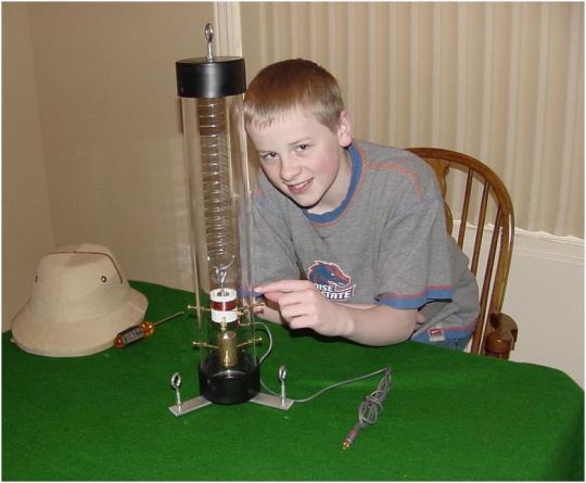
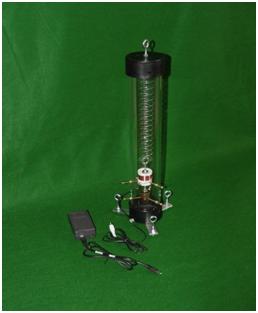
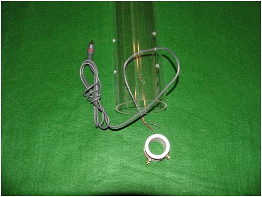
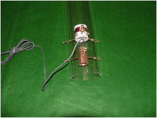
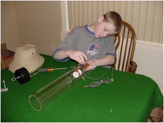
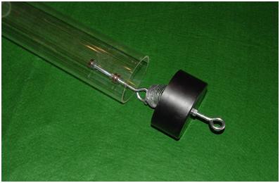
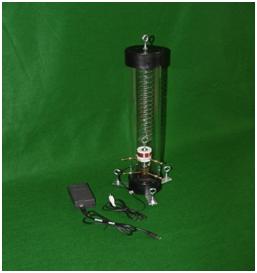
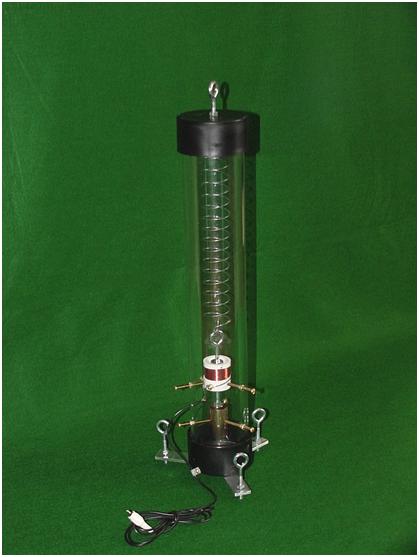
This version eliminated the ABS and the two ABS tees and replaced them with a single piece of 3.5″ OD acrylic tube, in this case 20″ long. 1/8″ wall thickness.

However, this could be any length you wish, which would give you a longer period. A 48″ or 60″ may require a heavier base to keep from tipping. You could also use a short section of acrylic and a longer section of 3″ ABS for a longer tube.


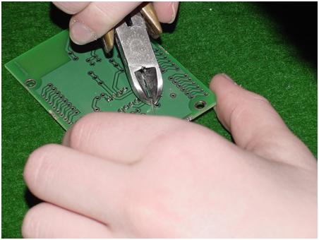
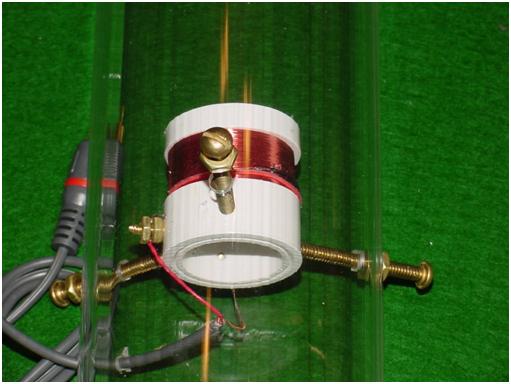
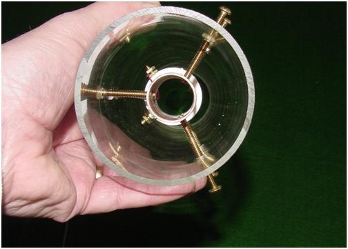
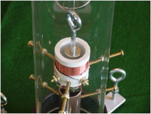
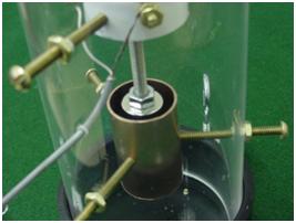
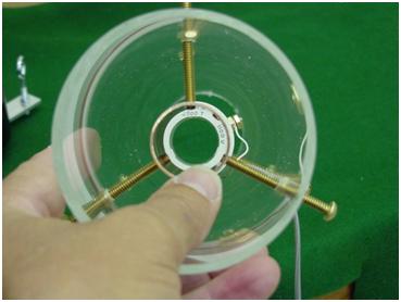
The coil and the damper are held in place using three each, #10 -24 x 2″ brass machine screws. The acrylic tube is drilled for these, using care not to crack the acrylic. On this 20″ tube, I drilled three for the coil at 5.0″ and three for the damper at 2.5″ from the bottom of the tube, all at 120 degrees, 7/32″ or ¼” bit.

You want a bit of play in the hole, so you can shift the part to the center line.


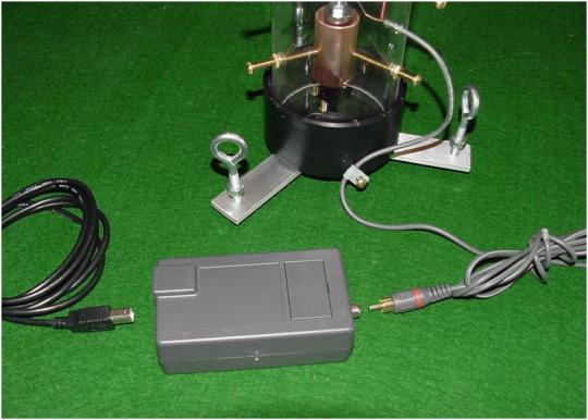
Drill a hole for the cable, to fit the cable diameter.


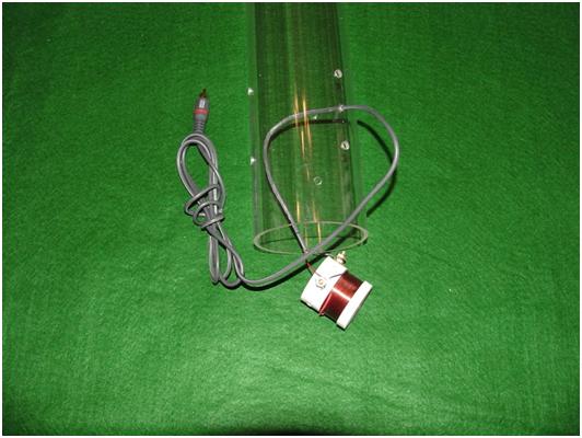
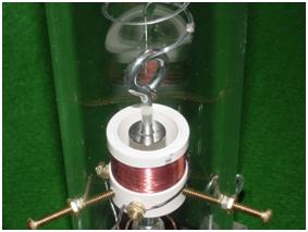
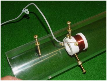
The coil is the standard Slinky type coil. In this case +/- 2500 turns of 38ga or 40ga copper magnet wire, and measured 700 ohms, to 2000ohms. The coil is made with a 3/4″ wrapped area.


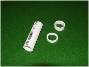
The coil body is 1″ id and 1.75″ in overall length. It is made of PVC plumbing fittings, cut to fit. Note: Use any 1″ pvc fitting, like a coupler for the rings. Use the thinner wall pvc pipe, 200 psi, and not the thicker pipe, for the body.


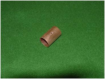
The damper plate could be a cylinder ring of aluminum, 1″id x 1.5″od x .750″ tall.

Or copper, using a 1″ id copper pipe, cut 2″ in length, or 1″ copper pipe coupler which is precut to 2″ length. Both the coil and damper are drilled and tapped for 10-24, 2″ brass machine screws, three places each @ 120 degrees.


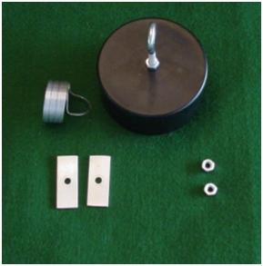
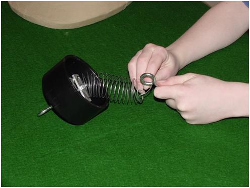
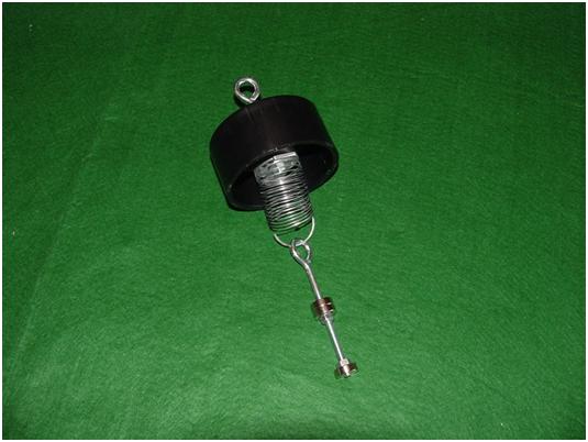
The spring assembly is made of a Slinky Jr. metal spring, cut in half in this case.

Use a full length Slinky Jr. spring for taller acrylic tubes. On this 20″ version, use approximately 15 of the coils. The remainder coils, retained with two alum, plates.


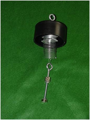
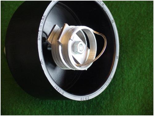
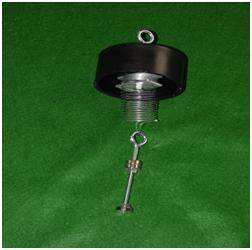
The spring is suspended from a ¼” 20 x 4″ eyebolt, nuts, and the 3″ ABS cap.


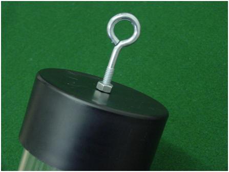
Use this eyebolt to make minor adj. to the magnet height.

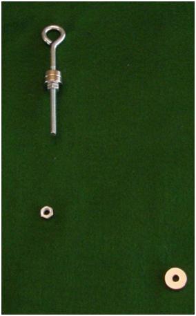
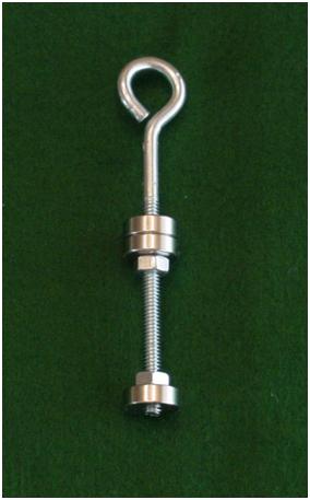
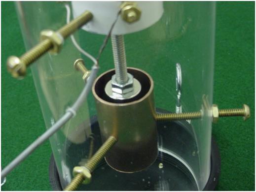
A ¼”- 20 x 5″ iron eye bolt holds three RC44 ring magnets and adjustment nuts. This hooks over a loop made in the bottom of the spring. Make sure the all magnets are NSNS……..NS, and the two nuts are positioned as shown below on the magnets. This allows for positioning the magnets up or down the rod.


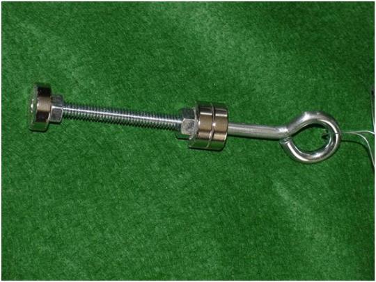
The neodymium magnets RC44, are ¼”id x ¾”od x ¼” thick. Two are used for the coil and one for the damper. The number of magnets used is optional. Their position on the threaded rod is adjusted using the adjustment nuts. On the coil both magnets should enter the top of the coil and the top of the top magnet should be even with the top of the PVC. This places one magnetic pole inside the coil and one magnetic pole outside. For the damper, the magnet should be even with the top of the copper, or ¼” inside. Proper damp is when the spring will bounce only once, or twice, not repeatedly.

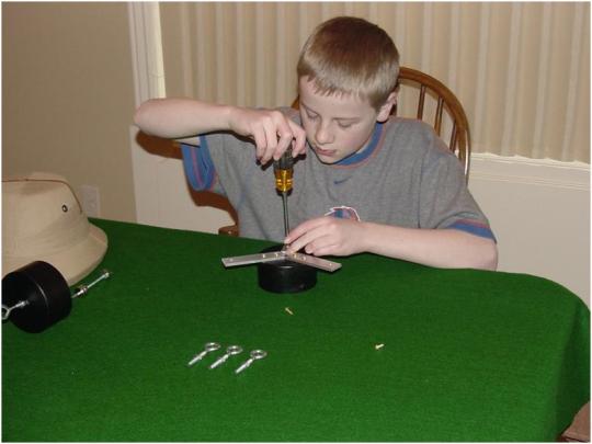
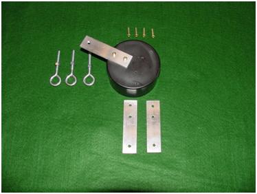
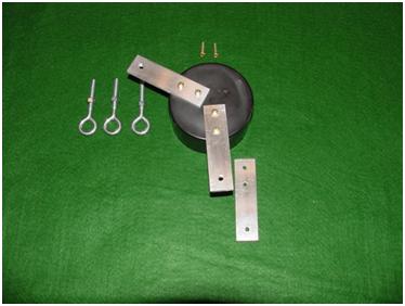
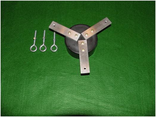
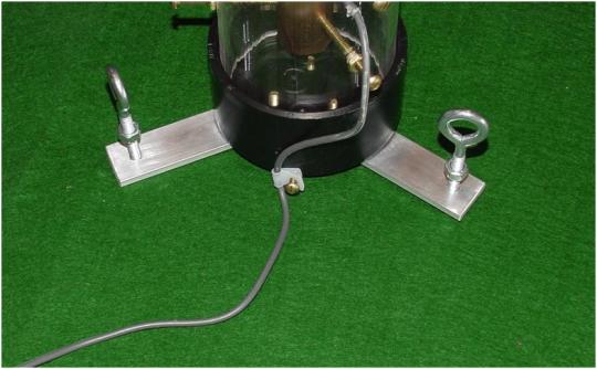
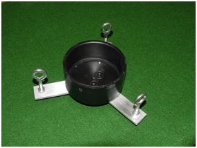
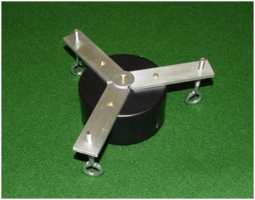
The legs and base are made using a 3″ ABS end cap. Drill and tap the cap, four places 8-32 for ¾”brass machine screws and a 1″ fender washer. The leg supports are made using 3/16″ x 1″ x 4″ alum. Drill one slip fit 5/32″ hole in each support, and angled the supports at 120 degrees. Drill and tap a ¼”x 20 in each support. The tapped hole is for the ¼”x20x3″ eyebolts and nuts for adj. legs.


Bill of Material:

Qty. Size Description

1 3.5″od x 20″ Clear Acrylic tube. You can use 1/8″ or ¼” wall. This tube can be longer.

2 3″ ABS Pipe Cap

1 1.5″ Slinky Jr. metal spring, cut in half.

3 ¼” id x3/4″od x 1/4″thick RC44 Neodymium ring magnets.

1 ¼” 20 thread 5″ eyebolt” Threaded eyebolt, to hold the three magnets

2 ¼” 20 thread Iron magnet retainer nuts, for the magnets

3 ¼” 20 thread 3″ eyebolts. Adjusting legs, these can be thumb screws,

Or 3″ eyebolts, with nuts.

Or Black knobs, etc. about 2″ long.

6 10 – 24 x 2″ Brass machine screws and nuts

1 ¼” -20 thread 4″ eyebolt Eye bolt, washers, and 3 nuts for the top cap.

2 Flat stock ¾”x2″ Alum. Retainers and nuts for spring coils

3 Flat stock         3/16″x 1″ x 4″ Alum. Leg supports.

1 700+ ohms coil Appx. 2500 wraps of 38ga or 40ga copper magnet wire. I target 700 to 1200ohms, using 2500 wraps of 40ga.

1 1″ pvc pipe x 1.75″long pvc Coil body, 200 psi, stock

  1. Pvc ¼”ring to fit coil body Cut from 1″ pvc coupler fitting

1 Pvc ¾” ring to fit coil body. Cut from 1″ pvc coupler fitting

2 6- 32 x ¾” studs Brass terminals for coil wires

4 6- 32 Nuts Brass connectors for coil wires

1 1″id x 1.5″od x .750″ Damper dough nut cylinder aluminum,

Or 1″id x 2″length copper pipe or copper coupler

1 6-10′ RCA Cable RCA cable, one end male one end stripped

4 8-32 brass machine screws to attach alum legs supports to base cap.

1 1″ fender washer to attach alum legs supports to base cap.


Other parts as required.


.


Jacob, Age 12
Feb. 25, 2012

Builds a Seismometer


Jacob, a 6th grader with a vision and a mission, from Lowell Scott Middle School, in Meridian, Idaho, sets out on an adventure to build a

SLINKY VIII

Seismometer and then record earthquakes near and far, from

around the world.


Can a man of limited years pull this off?

Boise State University, Dr. Van Wijk, Mr. Channel, and Jacob’s Mom think so,

and so does Jacob!


Chapter 1

An Overview

Jacob will need a computer with special software.

His teacher, Mr. Rosato, will provide that, with guidance from BSU.

His friend, Mr. Channel, will provide plans, encouragement, and hand him tools.

Jacob will need an amplifier that he will build from a “NERdaq Parts Kit.”

Jacob will need a seismic sensor. He will build it from a box of parts, called “Slinky Seismometer Parts Kit” provided by BSU.

He could have obtained it fully assembled, but Jacob wants to build it himself.

When it is finished, it should look something like this:


Chapter 2

The Amplifier

This very important part will amplify the faint electrical signal coming from the sensor’s coil. Like the sensor, the amplifier will be made from many small parts—electronic components soldered onto a printed circuit board.

Here are the electronic components:


Here is Jacob beginning the process of building the “NERdaq” amplifier.


He has a schematic, which is like a map or a set of directions showing where all the parts go. All the parts are in bags with their names and numbers on them.


This is a more technical view; Jacob will not need to understand all this, but simply place C5 through the holes in the board, marked C5. Really easy!


Here he is placing C5 (capacitor #5) into the holes on the board marked “C5”; R3 (resistor #3) into the holes on the board marked “R3,” and so on.


He will continue this process until all the parts have been inserted and soldered into place.

Here he is clipping off the excess wires from some of the components.


The finished printed circuit board attaches to the Arduino Uno, to complete the amplifier.


When he is finished, the amplifier will looks like this.


Chapter 3

The Slinky VIII Seismic Sensor

Jacob opens the box and finds all these parts, plus an installation assembly sheet.


He begins by assembling the 5″ eyebolt and three magnets.


First, two magnets go onto the eyebolt, and then one nut.


Next, the second nut, followed by the third magnet. All three magnets are stacked North-South, North-South, North-South. Now he assembles the top ABS cap.


The 4″ eyebolt and one nut go into the hole in the cap.

He flips the cap over, adds the second nut, and then one plate.


He inserts the second plate into the slinky spring, leaving about 17 coils below the plate. He inserts these over the 4″ eyebolt and secures them with a nut, finger-tight.

This forms a sandwich to retain some of the spring between the two plates, and some coils free to stretch. If more or less spring length is needed, he can change how many coils are below the plate.


He joins the Magnet assembly to the ABS cap by looping the eyebolt over the end of the spring.


The Base assembly:


As illustrated…………………..He attaches all three legs.


He flips the base over and adds all three feet……3″ eyebolts.


Assembling the Acrylic tube:

He inserts the RCA cable, from the outside into the smallest hole in the tube. The larger 6 holes are for screws. He pulls the bare ends of the wire out the bottom of the tube.


He attaches the coil to the two leads…..it does not matter which wire goes where, and finger-tightens both wires between the first and second nuts on the coil.


He inserts the coil and attaches the cable, from the bottom of the tube, up to the top three holes.


He inserts three brass screws through the holes and threads them into the larger white ring of the coil, three or four full turns are enough. Jacob makes sure to not thread the screws so far that they are visible on the inside of the white ring.


The large white ring of the coil faces down as shown:


He turns the tube so he can see down the center and positions the coil to the very center of the tube, like a Bulls Eye, then finger-tightens all three nuts to hold it in the center.


He repeats this process for the copper damper tube.

Adding three brass screws, he centers the copper tube and finger-tightens the three nuts.


Again, he makes sure not to thread these screws too deep into the copper, about one or two rotations is enough.


Looking down the tube again, he makes sure both the coil and the copper damper are centered in the acrylic tube.


Jacob now inserts the acrylic tube assembly into the base assembly and adds the small plastic clip to the base to secure the RCA cable.


Now he lowers the ABS cap with spring and magnets into the top of the acrylic tube.


The top two magnets need to be centered in the coil and not touching the walls.

The same for the bottom magnet, centered in the copper damper tube.


Jacob achieves centering, as seen from above, by adjusting the three legs, and when all the magnets are perfectly centered, the nuts on the legs can be finger-tightened.


The top of the two coil magnets, as seen from the side, need to be even with the top of the coil. This can be done by adding or subtracting coils of spring.

He can also turn the nut on the top cap, raising or lowering the entire spring/magnet assembly and, lastly, the magnets can be independently raised or lowered by threading them up or down the magnet eyebolt threads.

The damper magnet needs to be about even with the top of the copper damper tube.

Now he plugs the sensor into the amplifier, and the amplifier into the computer via the USB cable.

Jacob has just finished his Slinky VIII Seismic Sensor….


Once the USB is plugged into the computer containing the software,

AmaSeis, Winquake, and Arduino, and some drivers loaded,

Jacob sees his first signal, but it is just noise from footsteps.


However, later that night, an Earthquake: 6.8M in Siberia, Russia


Mr. Channel spoke with Jacob before, during, and after the building of this seismometer, and asked these questions:

1. Do you think you can assemble the NERdaq amplifier?

J: Yes, I do.

2. Have you ever used a soldering iron before?

J: Yes, I have when I did stained glass.

3. Do you think you can assemble the Slinky VIII sensor?

J: I’m a little nervous but I think I can do it.

4. After you finished, what was the easiest part?

J: It was building the base.

5. After you finished, what was the hardest part?

J: There wasn’t a hard part.

6. What changes to the “Slinky Seismometer Parts Kit” or instructions would you suggest?

J: I wouldn’t change anything.

7. Would your experience, doing the assembly, be helpful in training other students to build theirs?

J: Yes, I would be able to point them in the right direction.

8. How long did it take you to build the NERdaq amplifier?

J: It took about 15 to 20 min.

9. How long did it take you to build the Slinky VIII?

J: About 10 to 15 min.


10. What do you expect the seismometer to do?

J: Read the vibrations in the ground.

11. Who would you contact for questions about your new seismometer?

J: Mr. Channel
tchannel@cableone.net

12. Was it fun?

J: Definitely!


A few comments from Jacob to the readers:

I thought it was cool to set up the amplifier with the computer and tap on top of the Slinky VIII and watch the reader.

I touched the soldering iron to my finger and it dried out the skin there. It only stung a little.

I think my teacher should take the seismometer and use it in the future.

Jacob M.


BSU, Boise State University, Dr. Kasper Van Wijk, ssis@cgiss.boisestate.edu

His helper, Mr. Channel, tchannel@cableone.net 208-286-4787


Visit: http://cgiss.boisestate.edu/~kasper/geoph297wiki/index.php/BSU_Network


Here is a BSU site which tells where to get the software:

http://cgiss.boisestate.edu/~kasper/geoph297wiki/index.php/Home-built_Seismometer_Hardware_and_Software


Here are additional instructions:

http://cgiss.boisestate.edu/~kasper/geoph297wiki/index.php/

Slinky_Seismometer_Sensor_Assembly_Instructions


TC1 Seismometer Sensor Assembly Instructions


Remove sensor components from box. Remove top ABS cap containing spring. Hook eyebolt containing magnets over bottom of spring.


Insert and lower the magnet assembly into top opening of acrylic tube. Ensure ABS cap sits snugly on tube, but do not force it or damage tube. Position magnet assembly inside white coil and copper damper. Top of magnet assembly should be even with top of white coil body. One magnetic pole should be inside coil body and one magnetic pole outside.


Damper magnet height should be about even or ¼” higher than top of copper damper tube. Heights are set before shipping, but if correction needed, turn magnets and nuts up or down eyebolt.


Use three adjusting legs on base (at right) to center magnets

like a bulls eye inside coil (A) and damper (B), with equal free space all around. Magnets must not touch inner walls, or

sensor will appear to be working but will never record an earthquake. Periodically, ensure everything is still centered. Spring can stretch or turn over time, so corrections may be needed.

A B


Plug sensor RCA cable into BSUdaq amplifier box; plug USB cable from BSUdaq amplifier box into computer.

Load three software programs onto computer:

AmaSeis: http://pods.binghamton.edu/~ajones/AmaSeis.html

Winquake: http://psn.quake.net/software.html#WinQuake

Arduino: http://arduino.cc/en/Guide/Windows

Set up email account to receive USGS earthquake notifications: http://earthquake.usgs.gov/

At left under the heading, Latest Earthquakes, click on Subscribe Earthquake Notification Service and follow directions for setting up an account.

For questions contact: tchannel@cableone.net or  mailto:ssis@cgiss.boisestate.edu/